
Definition & Meaning
The term "3V 5V 5MHz to 133MHz" usually refers to the operating specifications of a particular electronic device or circuit component. These values indicate the voltage range and frequency that a device like the NB3N2302 Zero Delay Buffer can handle. Specifically, "3V 5V" denotes the allowable voltage levels, while "5MHz to 133MHz" describes the frequency range the device can operate within. Such components are often used in clock generation and distribution circuits, especially in high-speed computing and communication systems.
Key Elements of the 3V 5V 5MHz to 133MHz
-
Voltage Flexibility: Devices that support both 3V and 5V power supplies can be used in varied applications where either voltage level might be required, offering flexibility in design.
-
Frequency Range: The capability to operate from 5MHz to 133MHz is ideal for various applications, such as PCI-X and network interfaces, where reliable clock distribution is crucial.
-
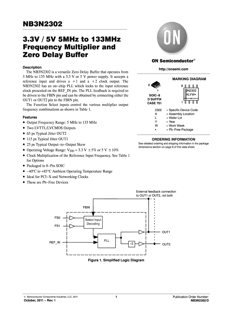
On-chip PLL: Features like an on-chip PLL for phase lock ensure minimal jitter and skew, making such components highly reliable for synchronous operations.
-
Output Types: Typically, these components provide LVTTL/LVCMOS outputs, which are standard for interfacing with various digital circuits.
How to Use the 3V 5V 5MHz to 133MHz
To utilize a device this specification refers to:
-
Select the Power Supply: Determine whether your application requires a 3V or 5V power source. This choice depends on the voltage levels of other components in your circuit or system.
-
Verify Frequency Requirements: Ensure that the component's frequency range suits your specific application needs, whether for a clock generator or a signal processing task.
-
Integrate with External Feedback: For applications needing clock synchronization, connect the external feedback paths correctly to facilitate accurate frequency multiplication.
-
Finalize Circuit Specifications: Incorporate LVTTL/LVCMOS outputs based on the logic level requirements of your associated devices.
Important Terms Related to 3V 5V 5MHz to 133MHz
-
PLL (Phase-Locked Loop): A control system that generates a signal that has a fixed relation to the phase of a reference signal, crucial for synchronization.
-
LVTTL (Low-Voltage TTL): A signaling standard used for compatibility with TTL logic at lower voltage levels.
-
LVCMOS (Low-Voltage CMOS): A common output format for modern logic devices, providing compatibility with a wide range of digital circuits.
-
Zero Delay Buffer: A key feature in clock distribution networks, ensuring that the delay in clock signal distribution is minimized.
Legal Use of the 3V 5V 5MHz to 133MHz
In the U.S., electronic components operating within specified voltage and frequency ranges must comply with national safety standards. Compliance with guidelines from entities such as the Federal Communications Commission (FCC) ensures that devices do not disrupt communication networks. It's also essential for devices to adhere to environmental and safety standards, as outlined by organizations like Underwriters Laboratories (UL).
Examples of Using the 3V 5V 5MHz to 133MHz
-
Networking Equipment: Devices like routers and switches often rely on such components to manage various data speeds and ensure synchronous data packet delivery.
-
PCI-X Cards: These cards, used in high-speed data environments, require precise clock reference signals to function correctly, which is achievable with devices operating in the 5MHz to 133MHz range.
-
Industrial Automation: In environments where precise timing is necessary for operation, such as in robotic arms or assembly lines, components with these specifications help maintain operational efficiency.
Software Compatibility
Components specifying "3V 5V 5MHz to 133MHz" can integrate with popular design software suites used by engineers, such as:
-
SPICE Simulators: For analyzing and optimizing circuit behavior under the specified voltage and frequency.
-
PCB Design Tools: To ensure that printed circuit boards support components that utilize these voltage and frequency parameters.
-
Modeling Software: Tools like MATLAB and CAD software assist in simulating the performance characteristics of these components in a system.
Business Types That Benefit Most from 3V 5V 5MHz to 133MHz
-
Tech Firms: Innovators in computing and communication equipment heavily rely on such components for designing upgraded electronic devices.
-
Manufacturing Companies: Industries focusing on electronics assembly utilize these components to build reliable and efficient machines.
-
Research Institutions: Developing experimental technology requires components that offer flexibility in power and frequency parameters, aiding in diverse applications and testing scenarios.